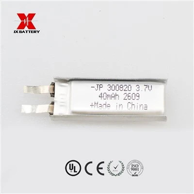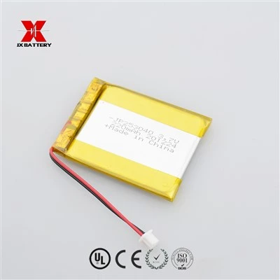


Many teams pick a cell labeled "fast charge compatible" and still see the case slow down near 90%, run unevenly warm, or charge differently with different adapters. In most of these cases the cell is not the culprit. The charging circuit settings and the input source were never matched to the cell. If you are designing around a Lithium Polymer Battery JP802025 350mah PCB Added or a smaller format, this guide shows how to check the whole chain, not only the battery.The Charging Chain Input, Charger IC, Protection Board and Cell
What Each Part Does
A TWS charging case charging circuit has four main parts:
Input source: a USB port, adapter or wireless coil that supplies power
Charging IC: controls the charging current and voltage
Protection board: cuts off in case of overcharge, overdischarge, overcurrent or short circuit
Cell: stores the energy
Why Supports Fast Charging Is Not Enough
A cell can accept 1C, yet the case will still charge slowly if the charging IC is set to 0.3C, the adapter cannot supply enough current, or the temperature sensor limits the current. Fast charging is a property of the whole chain.
Reading the CC/CV Charging Profile
A CC/CV charging profile for lithium polymer battery cells has four stages. The table shows commonly used settings, applied to a 350mAh cell. Actual values vary by charging IC and cell specification.
|
Stage |
Typical setting |
350mAh example |
|
Pre-charge (very low voltage) |
about 0.1C |
about 35mA |
|
Constant current |
0.5C to 1C |
175 to 350mA |
|
Constant voltage |
about 4.2V |
current gradually falls |
|
Termination |
about 0.05C to 0.1C |
about 17 to 35mA |
Why Charging Slows Near 90%
During the constant voltage stage, the voltage stays fixed while the current tapers down. The last part of the charge therefore takes noticeably longer, which is why many charging cases show "almost full" and then seem to crawl. A higher termination current ends the charge sooner but leaves the cell slightly less full, and a lower one gives a fuller charge at the cost of time.
How the Input Source Sets the Ceiling
USB Input
At 5V, a 350mA charge current needs about 1.75W of input power, and a standard USB port rated at 500mA supplies about 2.5W. That is enough for a 1C charge of a 350mAh cell with some margin for conversion losses. Three input parameters are worth confirming:
Input voltage range
Input current limit
Whether the adapter output stays stable under load
Wireless Charging
Wireless charging loses more energy as heat than a cable, and efficiency is commonly quoted in roughly the 60% to 80% range depending on coil alignment and design. That extra heat lands inside the case, so wireless designs usually need lower charge currents or better thermal management.
Matching JP802025 and JP301324 to the Circuit
Model numbers in this format are commonly read as thickness × width × length in millimeters. Please verify exact dimensions against the current datasheet before design freeze.
|
Item |
JP802025 |
JP301324 |
|
Approx. size (mm) |
8.0 × 20 × 25 |
3.0 × 13 × 24 |
|
Capacity |
350mAh |
90mAh |
|
Current at 1C |
350mA |
90mA |
|
Pre-charge at 0.1C |
about 35mA |
about 9mA |
|
Termination at 0.1C |
about 35mA |
about 9mA |
The 350mAh Cell
The Lithium Polymer Battery JP802025 350mah PCB Added suits mainstream TWS cases. A charge current between 0.5C and 1C keeps the case within normal thermal limits, and a standard USB input covers it comfortably.
The 90mAh Cell
Lithium Polymer Batteries JP301324 90mah needs extra care on the circuit side. Its 1C current is only 90mA, and its pre-charge and termination currents are single-digit milliamps. Some charging ICs cannot be set that low, so check the minimum programmable current before choosing the chip.
Temperature Sensing and Protection
The NTC Sensor
Many designs use an NTC thermistor to sense cell temperature. Placement matters: if the sensor sits far from the cell, the charging IC reacts late, and if it sits near a hot component, it may cut charging too early. Lithium polymer cells are commonly charged within roughly 0 to 45°C, and charging below freezing should be blocked.
Protection Board Thresholds
Set the protection board's overcurrent threshold above the charging IC's peak current, or the board will interrupt charging repeatedly. Overcharge cutoff is commonly around 4.25V for 4.2V-class cells.
Shipping compliance also deserves early attention. Lithium cells are generally required to pass the UN 38.3 transport tests before moving through most air and sea channels, and many platforms now request the report. Suppliers who keep this documentation current, together with consistent batch records, make launches smoother.
FAQ
Q: What charging current should I use for a 350mAh lipo battery?
A: A common range is 0.5C to 1C, which is 175 to 350mA. Higher rates are possible only if the cell datasheet and test data support them.
Q: Can you charge a lithium polymer battery directly from USB?
A: Not directly. A USB port supplies 5V, so a charging IC is needed to convert it into the correct current and voltage profile for the cell.
Q: Why does a charging case stop charging at around 90%?
A: During the constant voltage stage the current tapers down, so the last portion takes longer. The termination current setting also decides when the charger declares the cell full.
Q: Is wireless charging worse for the battery than a cable?
A: Not inherently, but it generates more heat because of conversion losses. Designs with wireless input usually need lower charge rates or better thermal design.
Q: Can the JP802025 and JP301324 be customized for my charging IC?
A: Protection board settings and dimensions can often be adjusted within a reasonable range once we know your charging IC and input specification. Changes to electrode formulation usually need new tooling and a longer lead time.
Does Your Charging Case Circuit Have a Matched Battery
If you can share your charging IC model, input specification and case cavity size, we can review the match and arrange samples for testing. For projects that need a customized design, we are also glad to discuss a TWS charging case battery OEM arrangement alongside your circuit